The PourMyBeer screen can be installed in 3 different configurations. This allows design flexibility within your individual build-out requirements.
Portrait – Attached Reader:
Configurable for 1 tap only
Portrait – Detached Reader:
Configurable for 1 tap only
Landscape – Detached Reader:
Configurable for 1 – 4 taps
Each TTG X9 comes with a mounting plate which the TTG X9 is then secured to.
Portrait: Position the open end toward the bottom
Use #6 Screw Flat head screws to mount the Screen Frames to the Tap Wall. Screw depth will depend on the backing materials used.
Landscape: Position the open end to the left or right side.
Mounting Tool: Each frame comes with a mounting tool (pictured below). This is used to keep the frame square with the correct distance between the lower mounting points. If the mounting tool is not used to square the screen frames then you will have fitment issues when installing the screens.
Screen Spacing (by Orientation):
There must be a cavity with 4″ of depth (minimum) for the screens to be installed into your Tap Wall
Be sure to adhere to the screen spacing requirements outlined above.
RFID Readers and Tap handles should be no higher than 48” for ADA compliance.
RFID Readers should NOT be mounted in metal.
120V Power outlets should be located within 4’ of the screens and there should be unobstructed access between the 120V outlet and the screen that will be receiving power. I.E. no studs blocking the cable drops.
Holes must be cored into the cooler behind the screens so the control valves and flow meters can be wired into the back of the screens.
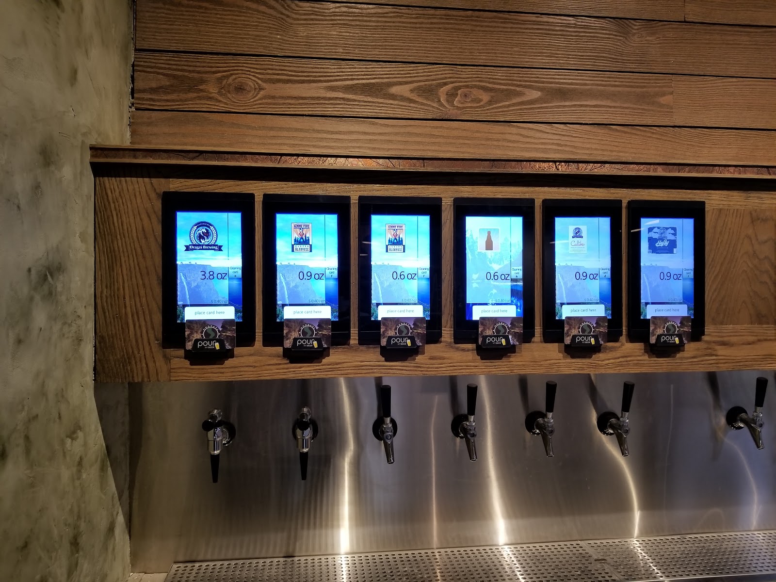
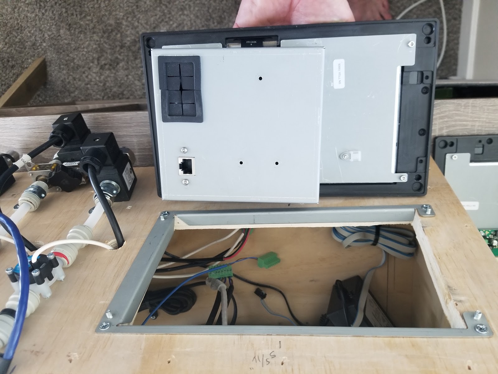
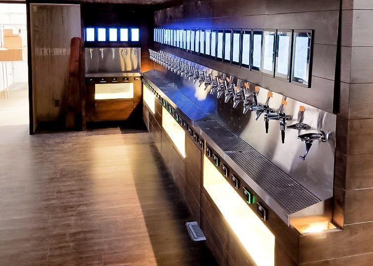
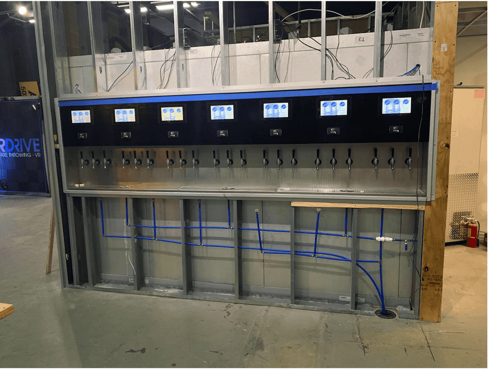
The photo above is a Tap Wall buildout with a Direct Draw Draft System. For Direct Draw Systems the simplest way to provide power and network access is to locate it all on top of the cooler. This way the power leads and network cables can be dropped down directly to the screens. The Network Switch and UPS Battery backups will all be on top of the cooler if built like this.
MoreThe Screens are attached by 4x 1.5mm Allen grub screws. These grub screws are tightened against the 4 dowel pins that are integrated into the mounting plate. The 1.5mm grub screws are located on the top (2) and bottom (2) of the screens.
Landscape: In order for the images to be portrayed correctly, the Screens must be installed with the cable box positioned to the right hand side of the screen cutout.
Portrait: the cable box should be positioned at the top of the screen cutout.
The External Readers are mounted into a polycarbonate housing. The housing itself is mounted with a removable backing plate. The RFID Readers MUST NOT be mounted on or into a metal surface. The metal causes signal interference and results in intermittent reads when an RFID card is placed on the holder. To maintain ADA compliance RFID readers should be no higher than 48” from the finished floor.
The RFID reader cable is approximately 32” long. A ⅝” hole must be drilled through your mounting surface behind the hole of the backing plate. The ribbon cable runs through this hole in the backing plate to the back of the TTG X9 control board. The ribbon cable connects to the top-board through a pin connector. The colored line on the cable must line up with Pin #1 on the control board.
Readers ready to be mounted onto the backing plate.
This guide will help you understand the proper way to wire the TTG Screens. Review the diagram below for all proper connection to the TTG board.
1. Power Supply In: This is the power coming in from the transformer. Right or left connection order does not matter.
2. Power Supply Out: This is used to power additional screens. You can only daisy chain if the total number of valves on being powered is 4 or less.
3. Fluid Control Valve: Each valve will be a pair of blue and brown wires. Valves are numbered from right to left just like flowmeters (diagram shows connection in valve 1 used). The wires can go in any order, as long as you keep a consistent pattern all the way through for every valve.
4. Flowmeter: The diagram below illustrates the proper connections for the flowmeter, you will match the wires from the flowmeter to the labels on the flowmeter section on the board.
1. Smart Fob: Like all other connections on the board, Smart fob connections are numbered from right to left (diagram shows line 4 being used). Connect the blue and brown cables like shown above.
2. Card Reader Ribbon Cable: The card reader ribbon cable will always have a colored line, ensure this colored line is connected to the left of all other connections.
For your safety always ensure the power source has been disconnected when making modification to the wiring of the TTG board.
Kickstart your self-pour journey! Access resources, checklists,
templates, and more to navigate and succeed with self-pour technology.
© 2023 Innovative Tap Solutions. All Rights Reserved. Sitemap | Privacy Policy