Integration of Valves and Flowmeters
PourMyBeer System & Flowmeters
The valves and meters count and control the dispensing of beer in ounces at the taps. Pay close attention to how these are installed. The Valves are directional, the flowmeters are not. Proper installation of the control device has a direct impact on the success of your installation.
Beer should flow from the keg, to the fob, then to the flowmeter, next to the valve, and end at the faucet. This process is illustrated in the diagram below.
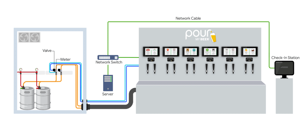
Your Draft system should be designed to include the following:
1. Fobs (Foam on Beer Detectors):
This prevents your customers from getting sprayed with gas and beer when the keg is depleted.
An example of a good Fob can be found here.

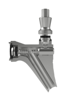
2. Trigger Tap Style Faucets (recommended):
These are binary (on / off) faucets that only allow the taps to be open or closed. This prevents a foamy pour from only slightly opening the tap.
3. Restriction
There should be enough restriction and pressure in the beer lines to result in a 1-1.5 second per ounce pour time (about half the speed of a normal bar faucet). We need the flow of beer to be slowed way down for the average customer.
• Blended Gas is required
• Pressures are typically around 22psi
• The system will require more restrictions to achieve the desired pour times.
4. Placement of Valves and Meters:
The Valve and Flowmeter assemblies MUST be installed below the taps and as close as possible to the screens. These MUST be installed in the Walk-In Cooler or Kegbox. The actual location may vary due to site restrictions and draft system design. Verify your design with a Project Manager prior to installation. Installing the valve assemblies above the taps (may) result in a pilferage issue at the taps. This is where the customer can pull the tap handle (without presenting an RFID card or wristband) and scavenge free beer. The amount of beer that is scavenged would then be charged to the next customer that presents their RFID card or wristband.
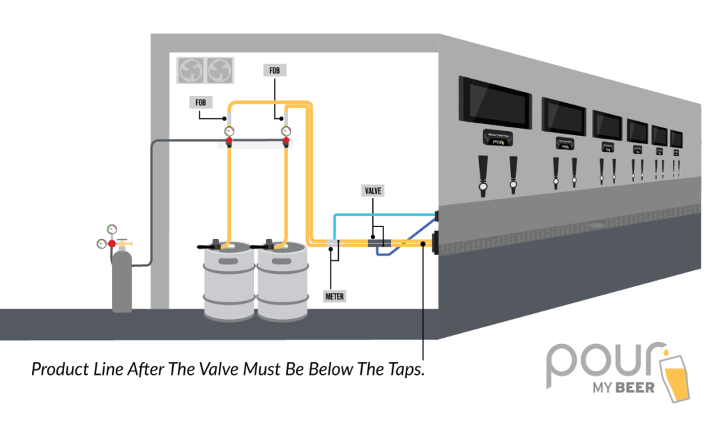
Long Draw: Integrated Valve
• Beer Lines below the taps and between Keg and Valves Assemblies
• Glycol Chilled
• Valve Assemblies less than 50’ away from the PourMyBeer Screens
• 4” – 6” of space between the Valve and Flowmeter Assemblies
• Access to Valve assemblies for day-to-day operations
• CAT6 Line run from each Valve assembly to each screen (numbered)
• Number each valve and flowmeter to the corresponding Tap for Identification prior to installation.
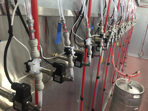
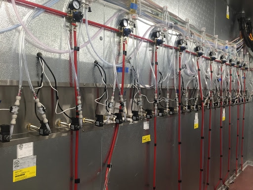
Example: The farthest tap from the cooler was 40’ at this location. CAT6 Lines were run to extend the power delivery from the screens to the valve assemblies. The beer lines exited the bottom of the cooler and ran down the base of the cabinet up to the taps.
Example: The farthest tap from the cooler was 40’ at this location. CAT6 Lines were run to extend the power delivery from the screens to the valve assemblies. The beer lines exited the bottom of the cooler and ran down the base of the cabinet up to the taps.
Long Draw Modified: Integrated Valve
• Beer Lines ABOVE the taps
• Glycol Chilled
• Valve Assemblies are more than 50’ away from the screens
• Auxiliary Cooler / Refrigerator to house Valve assemblies
• 4” – 6” of space between the Valve and Flowmeter Assemblies
• Access to Valve assemblies for day-to-day operations
• CAT6 Line run from each Valve assembly to each screen (numbered)
• Number each valve and flowmeter to the corresponding Tap for Identification prior to installation.
Example: The Walk-In Cooler was 200’ away from the Beer Wall at this location. A mini-cooler was built below the taps to house the valve assemblies. This prevented pilferage and provided ease of access for maintenance.
Example: The Walk-In Cooler was 200’ away from the Beer Wall at this location. A mini-cooler was built below the taps to house the valve assemblies. This prevented pilferage and provided ease of access for maintenance.
Long Draw: Isolation Valve
• Valves are installed in the trunk line (not recommended or covered under the PourMyBeer service level agreement)
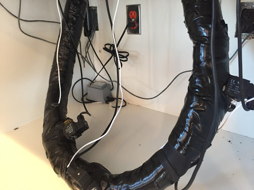
• Valve Solenoid MUST NOT be wrapped in the trunk line
• When the Long Draw Valve Assemblies are installed in the Trunk Line the Valves MUST BE STAGGERED in a way that the valve assemblies are not touching each other in any way. (Primarily to avoid contact between a valve and a flowmeter.) Installing the valve assemblies on top of each other can result in Flow Meters counting without the valve being open due to electromagnetism.
• 4” – 6” of space between the Valve and Flowmeter Assemblies
• Access to Valve assemblies for day-to-day operations
• CAT6 Line run from each Valve assembly to each screen (numbered)
• Number each valve and flowmeter to the corresponding Tap for Identification prior to installation.
Example: Valve assemblies are installed in the trunk line. The beer is flowing UP to the Taps.
Example: Valve assemblies are installed in the trunk line. The beer is flowing UP to the Taps.
Direct Draw
• Threaded directly onto the back of the shanks
• 4” – 6” of space between the Valve and Flowmeter Assemblies
• Access to Valve assemblies for day-to-day operations
Example: Valves are threaded directly onto the shanks. The stainless steel shadow box is built directly into the beer wall so there is no air gap or unconditioned space. This keeps the beer at the appropriate temperature.
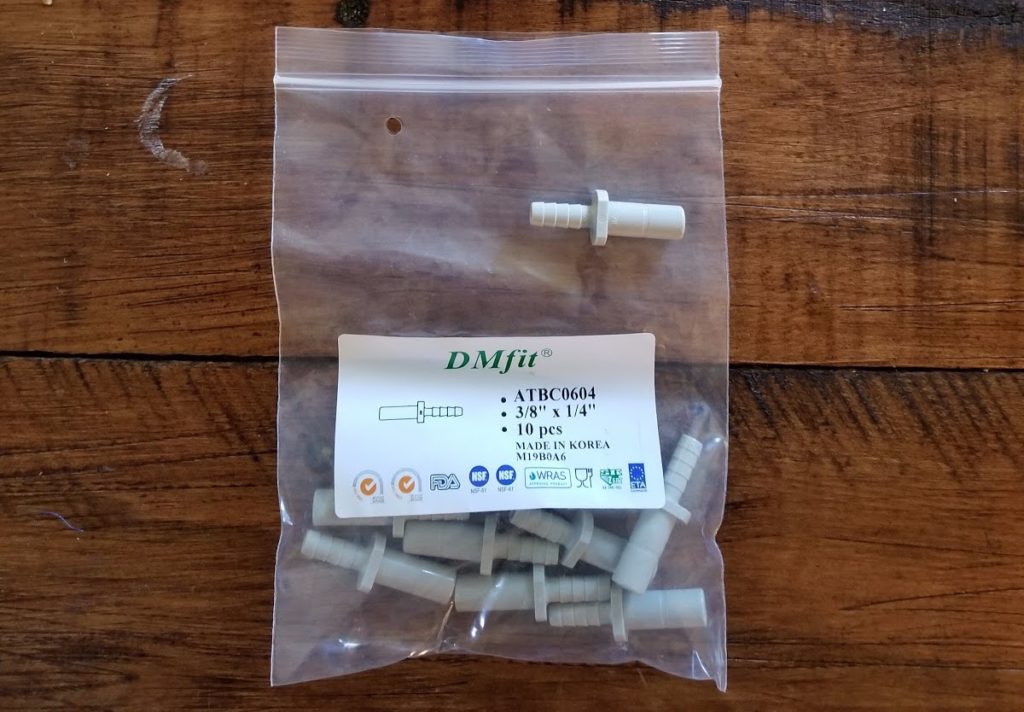
Long Draw Fittings: use ⅜” x ¼” Smooth to Barbed fittings for attaching the Long Draw Valve Assembly to your beer lines.
Direct Draw Fittings: use ⅜” x ¼” 90 degree Union Fittings fittings to attach to your beer lines.
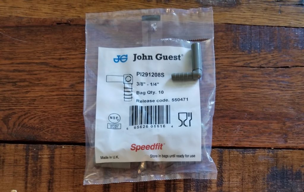
Union Fittings

Hard Line Tubing (between valves and meters)
¼” ID. It should be used for the 4” – 6” of space between the valve and flowmeters. This line will plug directly into a Union Fitting or the Integrated Direct Draw and Long Draw Valves.


